


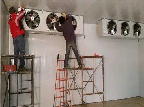
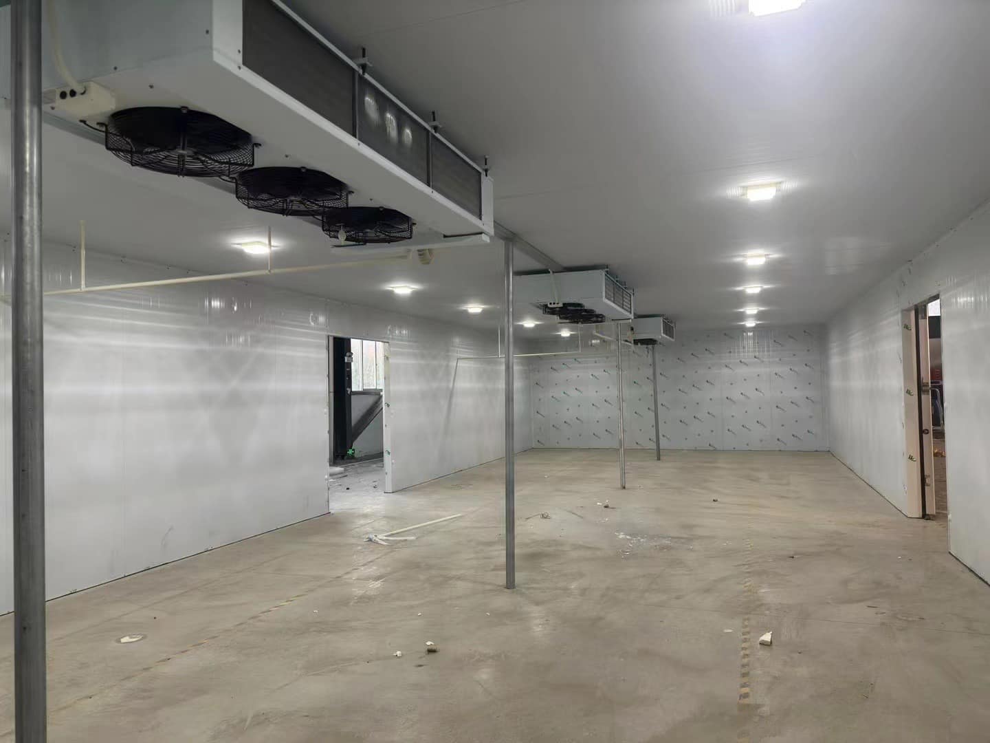
1-Installation of cold storage and air cooler
1. When choosing the location of the lifting point, first consider the location with the best air circulation, and then consider the structural direction of the cold storage.
2. The gap between the air cooler and the storage board should be greater than the thickness of the air cooler.
3. All the suspension bolts of the air cooler should be tightened, and sealant should be used to seal the holes of the bolts and suspension bolts to prevent cold bridges and air leakage.
4. When the ceiling fan is too heavy, the No.4 or No.5 angle iron should be used as the beam, and the lintel should span to another roof and wall plate to reduce the load.
2-the assembly and installation of the refrigeration unit
1. Both semi-hermetic and fully hermetic compressors should be equipped with an oil separator, and an appropriate amount of oil should be added to the oil. When the evaporation temperature is lower than minus 15 degrees, a gas-liquid separator should be installed and a suitable
Measure refrigeration oil.
2. The base of the compressor should be installed with a shock-absorbing rubber seat.
3. The installation of the unit should leave room for maintenance, which is convenient for observing the adjustment of instruments and valves.
4. The high pressure gauge should be installed at the tee of the liquid storage filling valve.
3. Refrigeration pipeline installation technology:
1. The diameter of the copper pipe should be selected in strict accordance with the suction and exhaust valve interface of the compressor. When the separation between the condenser and the compressor exceeds 3 meters, the diameter of the pipe should be increased.
2. Keep the distance between the air suction surface of the condenser and the wall more than 400mm, and keep the distance between the air outlet and the obstacle more than 3 meters.
3. The diameter of the inlet and outlet pipes of the liquid storage tank shall be based on the diameters of the exhaust and liquid outlet pipes marked on the unit sample.
4. The suction pipeline of the compressor and the return pipeline of the cooling fan shall not be smaller than the size indicated in the sample to reduce the internal resistance of the evaporation pipeline.
5. Each liquid outlet pipe should be sawed into a 45-degree bevel, and inserted into the bottom of the liquid inlet pipe to insert a quarter of the pipe diameter of the adjustment station.
6. The exhaust pipe and return air pipe should have a certain slope. When the position of the condenser is higher than that of the compressor, the exhaust pipe should slope to the condenser and a liquid ring should be installed at the exhaust port of the compressor to prevent shutdown
After the gas is cooled and liquefied, it flows back to the high-pressure exhaust port, and the liquid is compressed when the machine is restarted.
7. U-shaped bend should be installed at the outlet of the return air pipe of the cooling fan. The return air pipeline should slope towards the direction of the compressor to ensure smooth oil return.
8. The expansion valve should be installed as close as possible to the air cooler, the solenoid valve should be installed horizontally, the valve body should be vertical and pay attention to the liquid outlet direction.
9. If necessary, install a filter on the return air line of the compressor to prevent the dirt in the system from entering the compressor and remove the moisture in the system.
10. Before fastening all the sodium and lock nuts in the refrigeration system, wipe them with refrigerated oil for lubrication to enhance the sealing performance, wipe them clean after fastening, and lock the packing of each section door tightly.
11. The temperature-sensing package of the expansion valve is fastened at 100mm-200mm from the outlet of the evaporator with metal clips, and tightly wrapped with double-layer insulation.
12. After the welding of the whole system is completed, the air tightness test shall be carried out, and the high pressure end shall be filled with 1.8MP nitrogen. The low pressure side is filled with nitrogen 1.2MP. Use soapy water to check for leaks during pressurization, carefully Check the welding joints, flanges and valves, and keep the pressure for 24 hours after simple completion without dropping the pressure.
Post time: Mar-30-2023